GM Flow

FLOW MEASUREMENT

Flow Measurement

GM Flow Measurement Services have decades of experience in gas measurement. Building on our oil and gas sector experience, we recently pivoted into Hydrogen and CO2 as we all strive to reduce carbon emissions and develop non-polluting energy sources.

GM Flow design flow meters from the ground up. We use state of the art cloud computing methods, to analyse stress and fluid dynamics during the design stages. Finite Element Analysis (FEA) allows us to fully assess the flow meter body for stress levels prior to final pressure test and field operation. The most highly stressed parts are not always where expected, FEA allows us to thoroughly examine each design, focusing on specific areas of stress, modifying the design and / or material when required, with a high degree of confidence.
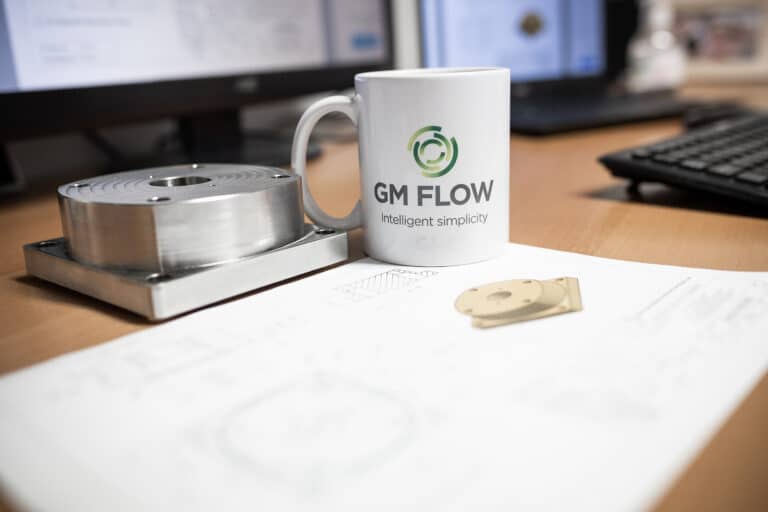
Gas flow meter technical drawing on desk
two employees discussing design of gas flow meter

Fluid behaviours within the flow meter body are evaluated, through extensive Computational Fluid Analysis studies, carried out both inhouse and by our chosen CFD partner, TŰV NEL. Many hours of CFD studies on each of our flow meter designs has taught us how each meter design behaves with water, natural gas, nitrogen and now hydrogen and CO2. High and low pressures, varying flow rates and different beta ratios are analysed so that the internal fluid path can be optimised for flowing velocity and differential pressure.  

Erosion and vibration studies provide assurance that our meter components will not be damaged by excessive flow velocities during use. Some flow meter manufacturers have made the mistaken assumption that what works in one size, pressure, beta ratio or fluid type will automatically work in every application. This has resulted in some cone failures, failures which GM Flow refuse to allow through diligent assessment and analysis.

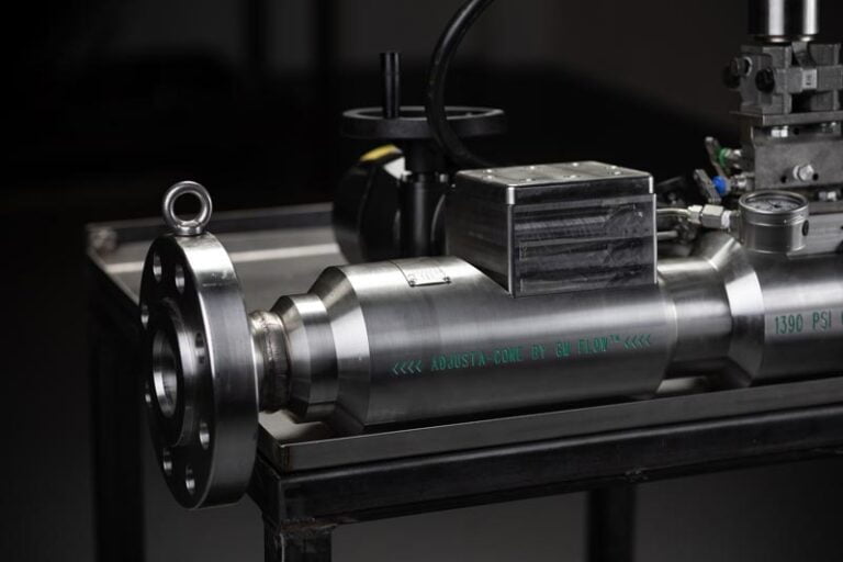
Adjusta-cone flange
Calibrating Adjusta-cone

In addition to our in-depth analysis, we verify using physical fluid flow calibration. When this is not possible due to safety concerns, as can be the case with natural gas, we test each flow meter with a comparable gas such as nitrogen. The calibration provides an equivalent Reynolds number range, with a coefficient of discharge for each point. This multi-point data is programmed into a flow computer, which during operation constantly calculates the optimum coefficient of discharge (Cd) for the given flowing conditions. Combined with a continuous gas properties calculation, such as AGA or GERG (density and viscosity) this maximises the accuracy of the flow rate measurement and reduces errors associated with single point calibration methods.

Further advances which are currently in our R&D pipeline include wet natural gas, high and low pressure hydrogen and smart CO2 metering developments. 

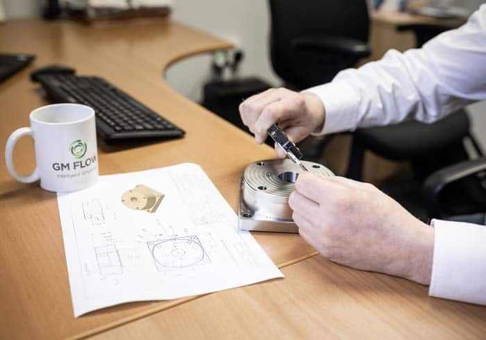
Engineer using vernier gauge to measure component of a gas flow meter
CFD being performed on a gas flow meter
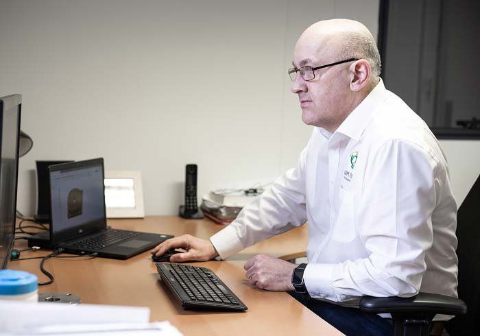
Male engineer working at computer screen